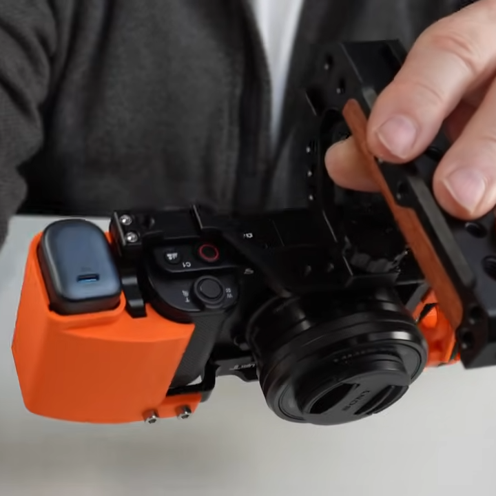
[John Dingley] has a Sony ZV-E10 camera that is excellent, but the design lacks a built-in electronic viewfinder. This means it relies entirely on its rear-mounted touchscreen for framing shots. This is troublesome because [John] often films in bright sunlight, and sometimes from a perspective other than normal eye level. His solution? Use a pair of XREAL video glasses as a handsfree viewfinder.
The XREAL glasses look a bit unusual, but they can be worn and used like regular sunglasses. They accept external video and importantly, allow the wearer to see the video feed while still having awareness of their surroundings. Seems like a perfect match for the camera, but as [John] discovered, there are quite a few implementation hurdles involved.
For starters, the camera and glasses do not speak the same format. The camera outputs HDMI via a distressingly fragile micro-HDMI connector, but the glasses accept video over USB-C (aka DisplayPort altmode). Connectors and cables and a converter will be involved, as well as a power bank because the glasses and converter will require a power supply. As any hacker knows, wires and connectors can eat up space very quickly.
To solve all this, [John] carefully selected off-the-shelf components chosen to minimize bulk and designed a custom camera cage to hold things cleanly without obstructing the camera’s microphone port. The end result is very tidy package that presents a single USB-C connection point between the glasses and the camera, requires no hardware modifications or soldering, and even takes the strain off the fragile connector on the ZV-E10.
The finishing touch is putting a neck strap on the XREAL glasses, allowing them to be easily donned and doffed as needed while filming. Check it out the video, embedded just below the page break.
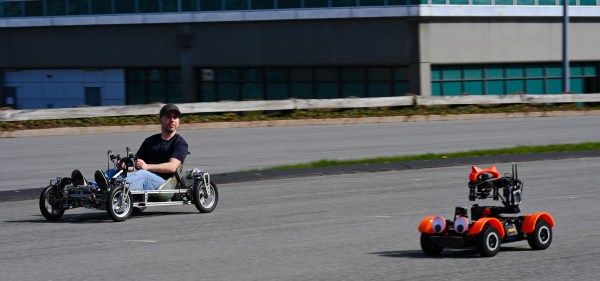
When it comes to filming vehicles it often makes sense to film from a low perspective. The camera has a handle for this purpose, but the process is much better now that the glasses can act as a viewfinder. [John] has a soft spot for vehicles, including self-balancing unicycles or monotracks of his own design.
Continue reading “Using Video Glasses As A Camera Viewfinder Is Harder Than It Looks”