555 timer circuit for the contest

Doing The Right Thing The Wrong Way: Dumping STM8 Firmware With 555 Timers

When [Jarrett] decided to enter the 555 Contest that’s just wrapped up, he leaned up on an idea that’s been rattling around in his noggin for a few years: Using 555 timers to trigger a firmware dump on a microcontroller. It’s definitely the wrong tool for the job, but [Jarrett] got it working and documented it nicely at Hackaday.io.

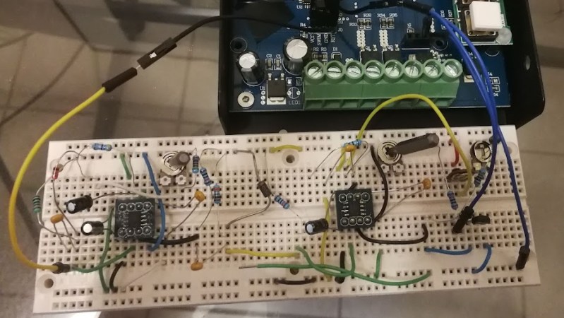
The premise is that by interrupting the power supply to the STM8 microcontroller at just the right time and for just the right duration, it would skip the instruction telling it not to allow its firmware to be read. Time and duration… things the 555 is well known for being capable of. There was a problem, however.

The first problem is that the duration was to be measured in nanoseconds. A garden variety 555 has can only pulse down to about 10 microseconds. The solution? Well, you’ll have to read the excellent project page to find out, but don’t worry- it’s a 555. The second problem? He was using 555’s!

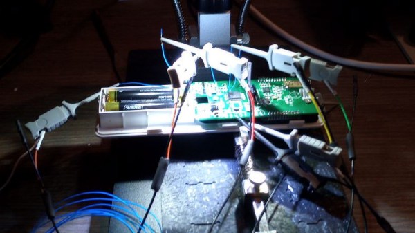
Was [Jarrett] successful? After much fiddling and twiddling, he absolutely was! The old firmware was dumped from the STM8 processor and the new firmware could be flashed with impunity.

This 555 contest has seen some truly epic entries, including but not limited to this 555 based accordion like instrument that this particular author just can’t get enough of!


An RF Remote Is No Match For A Logic Analyser!

The Neewer NL660-2.4 Video Keylight has a handy remote control, which for [Tom Clement] has a major flaw in that it can’t restore the light to the state it had during its last power-on. He’s thus taken the trouble to reverse engineer it and create his own remote using a suitably-equipped Arduino clone.

The write-up is a step through primer for the would-be RF remote hacker, identifying the brains as an STM8 and the radio as an NRF24 clone before attempting to dump the firmware of the STM8. As might be expected the STM is protected, which only leaves the option of sniffing the connection between the two chips. The SPI pins are duly probed with a logic analyser, and the codes used by Neweer are extracted. As luck would have it there is a handy board called the RF Nano which is an Arduino Nano and an NRF24 in an Arduino Nano form factor, so a proof of concept remote could be written on an all-in-one module. You can find the result as a GitHub Gist, should you be curious.

We’ve seen Tom a few times before, particularly in his European BadgeLife work, as part of which he’s put a lot of effort into bringing browser-based WebUSB and WebSerial development to his work.

A HALO Of LEDs For Every Ear

Few things get a Hackaday staffer excited like bunches of tiny LEDs. The smaller and denser the better, any form will do as long as we can get a macro shot or a video of a buttery smooth animation. This time we turn to [Sawaiz Syed] and [Open Kolibri] to deliver the brightly lit goods with the minuscule HALO 90 reactive LED earrings.

The HALO 90’s are designed to work as earrings, though we suspect they’d make equally great brooches, hair accessories, or desk objects. To fit this purpose each one is a minuscule 24 mm in diameter and weighs a featherweight 5.2 grams with the CR2032 battery (2.1 g for the PCBA alone). Functionally their current software includes three animation modes, each selectable via a button on device; audio reactive, halo (fully lit), and sparkle. Check out the documentation for details on expected battery life in each mode, but suffice to say that no matter what these earrings will make it through a few nights out.

In terms of hardware, the HALO 90’s are as straightforward as you’d expect. Each device is driven by an STM8 at its maximum 16MHz which is more than fast enough to keep the 90 charliplexed 0402 LEDs humming along at a 1kHz update rate, even with realtime audio processing. In fact the BOM here is refreshingly simple with just 8 components; the LEDs, microcontroller and microphone, battery holder and passives, and the button. [Sawaiz] even designed an exceptionally slick case to go with each pair of earrings, which holds two HALO 90’s with two CR2032’s and includes a magnetic closure for the most satisfying lid action possible.

As with some of his other work, [Sawaiz] has produced a wealth of exceptional documentation to go with the HALO 90’s. They’re available straight from him fully assembled, but with documentation this good the path to a home build should be well lit and accessible. He’s even chosen parts with an eye towards long availability, low cost, and ease of sourcing so no matter when you decide to get started it should be a snap.

It was difficult to choose just a few images from [Sawaiz]’s mesmerizing collection, so if you need more feast your eyes on the expanded set after the break.

Continue reading “A HALO Of LEDs For Every Ear”

A Unique Display Makes An Unusual Clock

Do you know the clock speed of the computer you’re reading this article on? Maybe Hackaday readers are more likely to reply “Yes!” to that question than the general public, but if there’s a takeaway it’s that for most computer users their clock speed is now an irrelevance. It’s quick enough for the job in hand and that’s all that matters. This was not always the case though, and a few decades ago the clock speed of a PC was its major selling point. Beige boxes would have seven-segment displays lit up with the figure, and it was an unusual example of one that [Ken Yap] used to produce a clock that he believes is one-of-a-kind; unless by some slim chance somebody else has rescued the same part.

The displays were hard wired without any signals from the processor, and what makes this one unusual is that as well as having a couple of digits in yellow it also sports a segmented “MHz” in red. This would have been quite a big deal on your 486 back in about 1994. To make a clock from this unpromising start required a little creative thinking, and he manages it by using the “M” and the “H” digits to represent minutes and hours, and displaying each figure in turn. The display is wired on a piece of protoboard with an STM8 dev board, and yes, as you can see in the very short video below the break, it does tell the time.

Custom displays are more usually seen in the world of LCDs than LEDs, so this one remains a rarity on these pages. Happily there are projects out there in which people spin their own takes on the idea.

Continue reading “A Unique Display Makes An Unusual Clock”

Pulse Generator Does The Job With An STM8

When working with hardware, whether a repair or a fresh build, it’s often necessary to test something. Depending on what you’re working with, this can be easy or a total pain if you can’t get the right signal to the right place. To eliminate this frustrating problem, [WilkoL] built a useful pulse generator for use in the lab.

[WilkoL] notes that historically, the job of generating pulses of varying length and frequency would be achieved with a smattering of 555 timers. While this is a perfectly cromulent way to do so, it was desired to take a different approach for the added flexibility modern hardware can offer. The pulse generator is instead built around an STM8 microcontroller; an unusual choice in this era, to be sure. [WilkoL] specified the part for its incredibly low cost, and highly capable timer hardware – perfect for the job.

Combined with an ST7735 TFT LCD screen, and programmed in bare metal for efficiency’s sake, the final project is installed in a project box with controls for frequency and pulse length – no more, no less. Capable of pulse lengths from 250 ns to 90 s, and frequencies from 10 mHz to 2 MHz, it’s a tool that should be comfortable testing everything from servos to mechanical counters.

Of course, if you need to get down to picosecond timescales, an avalanche pulse generator might be more your speed. Video after the break.

Continue reading “Pulse Generator Does The Job With An STM8”

Palm-Sized Sixteen Segments Light The Way To Our Hearts

It’s no secret that we here at the Hackaday are suckers for cool display. LEDs, OLEDs, incandescent, nixie or neon, you name it and we want to see it flash. So it fills us with joy to discover a new way to build large, daisy-chainable 16-segment digits, and even more excited to learn how easy they are to fab and assemble.

A cousin of the familiar 7 segment display, the 16 segment gives so many more possibilities (128% more possibilities to be exact) for digit display. To be specific, those extra segments unlock the ability to display upper and lowercase latin characters as well as scads of punctuation.

But where the character set is complex, the assembly is anything but thanks to a great design from [Kolibri] called klais-16. They’re available fully assembled if you want to jump straight to code, but thanks to thorough documentation (seriously, check this out) assembly is a snap.

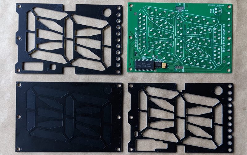
Each module is composed a very boring PCBA base layer which should be inexpensive from the usual sources, even when ordering one fully assembled. A stackup of three more PCBs are used for spacing and diffusion with plans for die-cut or injection mold layers if a larger production run ends up happening. Board dimensions for each character are 100 mm x 66.66 mm (about 4″ x 2.5″). Put together, each module can stand on its own or be easily daisy-chained together to make a longer single display.

Addressing all those bits with an elaborate, ugly control scheme would be a drag but fortunately the firmware for the onboard STM8 microcontroller exposes a nice boring serial interface which can be used without configuration to display strings. There’s even an example Windows Batch script!

The Cheap Way To Glitch An STM8 Microcontroller

Reverse engineering or modifying a device often requires you to access the firmware stored on a microcontroller. Since companies are usually not fond of people who try to peek into their proprietary data, most commercial devices are readout protected. [rumpeltux] ran into this problem when he tried to dump the firmware on an HC-12 wireless serial communication module for yet undisclosed reasons. Hacking into the device was a challenge that he gladly accepted and in the end, he succeeded by building a low-cost setup for voltage glitching.

Voltage glitching is a form of fault injection that has, e.g., been successfully used to hack the Playstation Vita. It involves the injection of voltage spikes on the power line in order to force the bootloader to skip security checks. The hard thing is trying to find the right shape of the waveform and the best way to inject the signal.

While there are already open-source boards for fault injection like ChipWhisperer, [rumpeltux] chose to build his own setup around an FPGA. By using a cheap EPM240 board, some MOSFET, and a USB-to-Serial converter, the total costs of the glitching setup were under 20 Euros. [rumpeltux] then recorded a larger number of voltage traces on the VCC pin around the reset phase and analyzed the differences. This helped him to pinpoint the best time for injecting the signal and refine the search space. After some unsuccessful attempts to glitch the VCC and GND pins, he got lucky when using one of the voltage regulator pins instead.

Be sure not to miss Samy Kamkar’s talk at Supercon 2019 if you want to know more about hardware attacks or how to eavesdrop on people using a bag of potato chips.