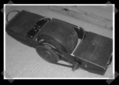
Fresh off the tip line, [Ben] sent in his one wheeled balancing scooter. It’s a nice simple design – I just might have to build one myself. The steel frame surrounds a pair of 12V 12Ah SLA batteries, a 400w 24v DC motor, one of the ever handy OSMC motor controllers, rate gyro, accelerometer and a PIC 16F876A. I love the entire concept! (For some reason, I’m thinking it needs a brake light on the rear…
Check out the video after the cut. He walks through the hardware at the end.
By the way, Eliot and I’ll be at Shmoocon in a couple of weeks. We won’t have boards from the Design Challenge yet, but we should have something to give away to people who find us there.


reminds me of the “back to the future” hover skateboard thing…
i think this is my new favorite thing on hackaday.
Ohhh man… I think this one of the coolest things EVER on hackaday… If only things like that weren’t banned in my school’s hallways!
Actually, the side impact air bags are much more important than the rear brake-lights.
this will replace the bike!
It’s a little lacking in the acceleration department…but the concept is amazing!
how does this thing turn with one wheel?
it turns just like a skateboard/snowboard. a slight shift in weight towards the outside ends will cause it to lean in whichever direction the person moves. if said person is good enough they can “carve” just like on a skateboard/snowboard. i like it, but is there a way to make it faster? perhaps a bigger motor and a speed control hooked up to a hand throttle/brake like a motorized skateboard? if it can be done, then im absolutely building one of these! great job, cheers
I know this is hackaday or whatever, but I really think guy should get a patent on that cause its a cajillion times cooler than a dumb ass segway, and looks like a simpler design. I’d hate to see some multinational come in and rip this guy off.
Im sure given the proper funding he could sort out the instability and probably get the weight alot lower.
Im thinking that some sort of regenerative breaking could be used on this to save energy.
This comment aged like milk 😔
Believe me, I’ve looked at patents. Unfortunately what I’ve made seams to be squarly covered by Segways patent, hence the publication of all that I’ve done.
The instability problem was more of a rider problem – the guy that has the wobble in the video was trying to step off by putting all his weight at one foot. I guess I shoul have described it a little better before letting him have a go.
It does regenerative braking. It’s inherent in the locked antiphase drive method used.
You couldn’t do much carving on that form of tire unless you over inflate it giving it a high center.
I was let down by his article. The controller, motor, frame are no brainers, but I really wanted to know the design of the axle, and what he used to fabricate it.
An even better design is to put smaller diameter wheels, or tires on each side.
I’ve found that the ability to turn (carve?) isn’t too dependant on tyre pressure. The deformation of the tyre and the formation of a triangular contact patch is what enables you to turn, a high centre is not required.
The axle was turned on a lathe. It’s a very simple design – I’ll put a sketch on the site tonight.
I’m not sure I agree with smaller wheels or one on either side. Having two wheels would require some kind of user input to determine the rate of turn, with one wheel you control the whole thing with your feet and movement of mass.
Can you imagine riding a snowboard with a potentiometer to control your rate of turn?
Very nice! I have always dreamed of a homebrew segway-like device. The drive portion of this reminds me of some electric gokarts out there, which have three-phase motors and fancy stuff like regen. braking.
On TV I saw a special, apparently segway made a four-wheeled (“quad”) segway that goes pretty fast. It would be interesting to see someone make something of this sort.
yes this is more like it we all need one of these best thing i have seen on here for a long time
hmm.just looked at the site, and it clearly reads 7Ah on the battery(picture) but it always says 10Ah. which is it now? its not a big deal, i just have some experience with using the wrong batteries on stuff, so to me it matters :)
anyways, great stuff!! too bad with the patents and all.. a friend had a similar problem with a mini35 adapter(p+s has patents on anything related)..
again: good job!
Very cool, just wanted to point to some other DIY balancing projects
Similar but with two wheels
http://www.ebikes.ca/projects/Emanual/index.shtml
Trevor Blackwell’s classic segway clone
http://tlb.org/scooter2.html
And his unicycle
http://tlb.org/eunicycle.html
Yours is very polished, good job!
Battery:
The battery is definately a 12Ah Sealed Lead Acid unit. Unfortunately the picture was taken from the rswww.com website who have a tendancy to show mismatching products / pictures.
If you’re planning to build one of these I’d carefully consider the battery. My scooter can draw well in excess of 50A when stalled. Under these conditions the rs battery (537-7305) voltage almost halves. In short, the battery that I have chosen is probably one of the weak points, although it has probably stopped me burning out the motor!
ben, this is really great.
how does it perform on slopes? at what point will it stall, and can you help give it a little push like a skateboard to help it up?
It performs well on slopes, with deck staying level. If you’re familiar with PID feedback control (Proportional, Integral, Derivative) then it’s the integral term that sorts hills out.
that is sweet! :)
Excellent work Ben, very cool. The only thing that looks tricky to me are the mount and dismount – how is it in actual use?
#12 I was suggesting smaller wheels on each end to handle over tilting at higher speed, and there diameter could also be factors in a fixed speed.
As for having stuff done on a lathe. I’ve found unless you have friends in, or with immediate access to a machine shop; having parts done from ether a CAD, or simple dimensional markup is a major headache, and in most cases expensive as hell(Probably why we don’t see decent formed metal parts on most entry level robotics projects.)
Metal stock is also expensive because so few sources sell it that they’re able to over charge because of the whole supply and demand model.
Also regarding patents. I know first hand that in the field of robotics, electrical engineering, and most other fields anything innovative you create is most likely gonna be covered by some greedy guts patent even if his design is barely similar to yours. Big corporations try to cover as many concepts as possible when they apply for patents, and there applications are usually approved quickly. The same applies to millionaires who decide one day they want to take advantage of consumerism through cheap components wrapped in injected molded plastic that entertain.
Wow! This is amazing. I live for EVs, so this might be something in need of my attention.
Are you willing to give me a hand, I can do the motor control driver, but I am absolutly sure I would need help with the stabilizer on the other side. I don’t quite understand how it works, purhaps you can give a write up about the physical and technical aspects of the stablizer controller.
Ben, you are a DIY-GOD.
Any chance for publishing more detailed blueprints and/or schematics?
why thankyou
I’m quite happy to publish more information, I have drawings for the axle and chassis which I’ll make available on the website. They’re very simple to make.
I’m quite keen to make this an open source project – kind of like the Open Source Motor Controller (OSMC). I’d be keen to hear from anyone that would like to be involved.
I have lots of ideas for improvements too.
Keep an eye on the website.
Maybe the wheel should be set further back so the rider is always putting more weight to the back (or front?) instead of trying to make equal weight to both feet. To reproduce the feeling of a surf board or skateboard.
Ben do you plan on releasing a more detailed “how to” or anything of the sort, to get us to build our own?
I get the general idea, but there are little things I still dont understand…
Absolutely, I’ll put some more information on the site over the next week.
first of all, this is the coolest thing ive seen in a long time, nice work. I think ill start building one myself.
how much torque does that motor have?
The motor has a rated output of 400 Watts at 1500 RPM. That equates to a torque 2.5 Nm at 1500 RPM. At lower speed a higher torque may be possible – the motor has a max continuous current of 21A, I have seen spikes of over 50A when I drive it too hard.
Congrats on such a simple, elegant design, and being the first to build it. It definitely falls into the category of “Why didn’t I think of that???”
I’ve seen plenty of self balancing scooters and robots, but this one has a whole new level of cool factor. It definitely loses the “nerd” stigma of other balancing toys/machines.
Very Impressive. I myself fell in love with the emmanual when I first saw it. But this takes some of the complexity out of that project and cost. I have a question for Ben. The Gyro and Accelerometer are not in packages that I would consider hobbist solding friendly. did you get demonstation boards to use these devices? Also I am like a lot of others a schematic on your web site would explain much more on you board. I love this project and I myself would also like to build one. I have been looking for a good balanceing robot/rider project. The setup for this one seems to be the simplest and definatly the most fun. Thanks for sharing your hard work.
Congrats on a job well done. I just moved to Norwich area and had checked this a few times before it dawned on me where you were :)
wow, honestly, would you consider making more of these and selling them to people? :O
I would do horrible and unspeakable things for the extra money to buy/make one of these. Great project, keep it up.
I love the project! Very interesting. Are there any other options besides the $200 OSMC? This seems to be by far the most expensive part of the project. Any other options?
I agree with the others.
This not only is a great project, but it’s so well executed that I almost want one too!
(I wouldn’t try it because I would kill myself)
Everything about it is not only logically engineered, but it all ends up being downright aesthetically pleasing as well! (at least to me)
The only (and I mean only) thing i could say is maybe add a couple of small wheels (bogeys) on the ends to handle occasional over-tipping but that’s it.
Too bad you didn’t make this the size of a business card, because you would have won the contest man. ;)
man, nice work! been living in Norwich for about ten years, and this is the most interesting thing i’ve seen from around here in all that time :)
maybe i could build one to get me to and from sixth form in style! so how steep a slope has it been up? tried grapes hill yet :)
So with the two batteries, how long does it run between charges? I assume the motor’s not running at its peak 40A all the time…
Awesome project, btw :D
This is a very nice project Ben. I’m very interested in building one myself. I live in Australia and build combat robots for a hobby, it was great to see some familiar parts in your project (OSMC controller, SLA’s, Go kart wheels and Scooter motors).
If your looking for further possible upgrades, http://www.oatleyelectronics.com.au has a nice range of scooter style motors. The 100watt and 300watt motors have proven very well in robot combat. The 250watt geared motors have proven to be very powerful, check out the 26kg Lightweight robot Maestro (http://youtube.com/watch?v=U0xxSkvqlXE youtube video) it’s charges the arena at around 12-15MPH…
Nice project, and keep up the good work!
What limits do the Segway patents put on this project?
You should start a forum for the discussion of making these things, it looks awesome, good job.
Hey Ben, awsome build! I’m so going to make my own!
Anyway got a question, what width is the tyre you used?
Excellent work! You mention a tendency to send the rider over the front when top speed is achieved. Is this due to the motor suddenly ceasing acceleration, or from the front of the device digging into the pavement?
If the former is the case, could you not put in a buffer circuit to lower power as top speed is approached, and restore the power as it runs out?
If the latter, then why not put small rollers (roller blade wheels come to mind) on the edge that would be first to contact? It would impede control, but at that speed, damped controls would probably be a good thing.
my .02
One last question: what are the approach and departure angles for this device? (the angles at which the surface would come into contact with the board, assuming the board is level)
where did you get your tire and what are the specs on the motor? also how do you get the “skateboard” ( i like to call it a motobord) to respond while going up a hill?
Thanks so much, for the useful post!!
I found a youtube video about xbox live hacks: that I would like to share: Xbox Live hacks!…
but seriously, amazing post and thank you allot !!
i look forward to your next post !!
;)
Normaal reageer ik niet op blogs, maar deze keer wil ik toch even aangeven dat het een mooie blog is!
Does Ben Smither have a website anymore?
Does anyone know where a tutorial to make this could be?
I’m really interested in making one of these
7 years later and someone is finally trying to make one for everyone to enjoy … http://www.kickstarter.com/projects/4422853/onewheel-the-self-balancing-electric-skateboard
I just wish they gave Ben some credit — a shout out would be the polite thing to do
I’m more interested on speed. What’s the max speed you can get from this?
Here I am in 2020 and I saw someone rolling down the road on one of these and remembered this hackaday article from more than a decade ago. Anyone know if this guy took his project and made a business out of it or did he just get cloned?
Likewise no idea. But this is one of those ideas that seems to have stuck in everyone’s brain.