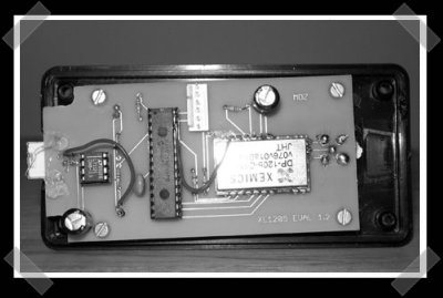
Since I mentioned Sparkfun electronics in the parts finding how-to, I started poking around their forums and stumbled across this interesting USB RF modem. It uses an off the shelf Semtec DP1205 RF module that’s controlled by a PIC 18F2550. The really interesting thing is that it uses spread spectrum frequency hopping – which means that by FCC rules, it can transmit up to 1 watt at 900Mhz.


17 thoughts on “Spread Spectrum Freq Hopping USB RF Modem”
Leave a Reply
Please be kind and respectful to help make the comments section excellent. (Comment Policy)


FHSS actually isn’t too uncommon a feature in COTS 900 MHz transceivers, precisely because of the FCC rule. Still, that’s an awesome little project. Handy, too. Who needs the wireless USB standard when we’ve got these? ;)
I’ve been looking for something like this, great article, however I’d really like to see one that uses OFDM simply for the bandwidth and other benefits it provides. 100kbps is a decent data rate for a diy project, however I’m fairly certain that it could be improved.
I wanna know what the range is on that baby. I’ve actually got a great use in mind if it’s far enough. But it’d have to be better than directional wifi, and I’ve seen claims that a cantenna can give a good 1 mile range.
the range on this could be enormous if you only add a off the shelf CB antenna
there are a few companies that sell really nice antennas specifically for the 900/915mhz ism band one of them is http://www.hyperlinktech.com, another is http://shop.defactowireless.com/s.nl/sc.2/category.251/.f
I’m sure theres more but heres a few
hmm this looks like just what i’m looking for to use for my computer-controlled lasertag project i’m working on…
thanks hack-a-day (and mainly to whomever came up with this excellent writeup)
#3, that might work for receiving, where any random length of wire can be used for an antenna, but sadly, thsts just not the case for transmitting antennas. Transmitting antennas must be designed for a specific frequency. For example a common equation equation for calculating antenna length for your average quarter wave dipole antenna (think rabbit ears) is 234/(freq in mhz)*12= length of antenna in inches.
So once you put that cb antenna on there you would have a horrible swr because a cb antenna is tuned for around 30 mhz and thus would be 93.6 inches long while this project works on the 900 mhz band which wants an antenna at 3.12 inches. As you can see, that antenna would be considerably too long, and you would run the risk of burning out your transmitter.
A better method would be to build a directional antenna such as a yagi (like your tv antenna on your roof) or cubic quad. Although, if I remember correctly, the FCC doesn’t actually care about the transmitter power, but more the effective radiated power, so if you have a 1 watt transmitter, and an antenna with 12db gain (remember: power doubles every 3 db) so thus you would have:
1 watt * (2)^(12/3) = 16 watts
so basically, you would be out of compliance with the FCC.
well, just my 2 cents.
73’s
KE5GQS
The same applies to the cantenna, which is tuned to around 2.4 GHZ, or 2400 mhz using an antenna at about 1.17 inches.
@6: You can tune a cantenna to various wavelengths; it’s just the idea of a Cantenna propagated with WiFi so they are generally tuned for 2.4GHz.
@ #5, ziggit
very informative! thank you
Can anyone find the RF module he is using? he says its a “Semtec DP1205 RF module” that uses a Semtec XE1205 transceiver, but i can only find info on the XE1205 chip, not the DP1205 module.
Hi. This is actually my project. I was surprised this morning by a huge increase in my website’s traffic. I thought I was being hacked, untill I realized hackaday was real.
To answer some questions:
1. The transmitter power is 15dBm which is comparable to off the shelf WiFi components so the range is very comparible. I’ve seen broadband amplifiers at Digikey for a few dollars that can do up to the limit of 1Watt but they are all very tiny SMT components and I am not advanced enough in my soldering skills for that.
2. The DP1205 is a dropin module for the XE1205. At the time I built this this was a regular stocked item at Digikey. Apparently, the sales volume has been low so now it is only a backorder item and minimums apply.
The documentation for the module is here:
http://www.semtech.com/pc/downloadDocument.do?id=1796
The documentation for the XE1205 chipset is here:
http://www.semtech.com/products/xe1205/
I’ll add more links to the website. As I say on the website, the modules do not contain a protocol layer. That is all done in C on the PIC.
#7 true, I suppose I was thinking of the store bought ones.
after some google, it seems that some people built theirs like a Yagi(well a bastard child of a yagi and the circular wave guide), but most seem to be circular wave guides.
on that note I found:
a handy yagi calculator:
http://www.saunalahti.fi/elepal/antenna2calc.php
a circular wave guide calculator:
http://www.saunalahti.fi/elepal/antenna2.html
and then there’s my personal favorite, the cubic quad:
http://www.softcom.net/users/kd6dks/quad.html
I actually hit a repeater about 30 miles away a cubic quad driven with my 1.5 watt ht.
how about linux implementation
What type of Spread Spectrum technology is this project using?
The project uses the frequency hopping type of spread spectrum, which means that the transmitter and receiver hop from frequency to frequency after short intervals( 200ms in this project ). The idea is that if inteference happens, it only happens for short periods of time. The other advantage is that a fixed frequency isn’t used so many of the same device can be in close proximity.
Wikipedia has an article on the technology:
http://en.wikipedia.org/wiki/Frequency-hopping_spread_spectrum
can you help me find out how to open a cell phone to monitor all the freqs it is using unmute it like a scanner,1900mhz etc,thanks
Does anyone has a copy of this project? Mike Zoran’s website is down and the Archive.org copy does not include files.