Part 2 can be found here
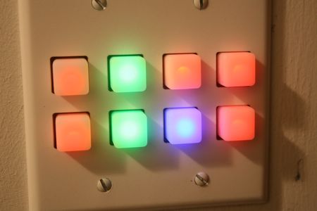
Putting a custom designed electronic lock on your space seems like a geek right of passage. For our latest workspace, we decided to skip the boring numbered keypad and build a custom RGB backlit keypad powered by an Arduino. Instead of typing in numbers, your password is a unique set of colors. In today’s How-To, we’ll show you how to build your own and give you the code to make it all work.

The basic design for the RGB keypad came from [JMG]’s Arduino based Monome clone. He used an Arduino, and multiplexed RGB LEDs with some digital potentiometers to create a color mixing keypad. Since we couldn’t fit the complete 4×4 keypad into a standard 2 gang wall box, we chopped the design down to a 2×4 matrix. This cuts down significantly on the cost to build the keypad and makes the code that much easier to digest.
To build your own RGB keypad, you’ll need the following:
- An electric door strike (Smarthome.com)
- A locking door handle (Any hardware store)
- An Arduino or compatible clone (Sparkfun, adafruit and others)
- 1 TIP120 transistor
- 1 1N4001 diode
- 10 1N4148 diodes
- 4 2n2222 transistors
- 1 Monome style keypad (Sparkfun Electronics)
- 1 Keypad PC board (Sparkfun Electronics)
- 8 RGB LEDs (Sparkfun Electronics)
- 1 7805 voltage regulator
- 4 100 ohm resistors
- 2 150 ohm resistors
- 8 1 kohm resistors
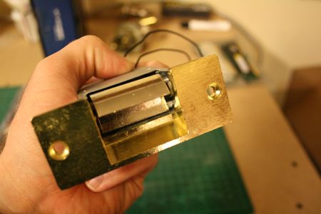
To reliably lock and unlock the door, we ordered an electric door strike. We scored this one as an open box item from Smarthome.com. It’s a 12 Volt DC unit designed just for Schlage commercial door locks. The edge of the strike is slightly recessed from the mounting plate, so it might not work with certain locks. It features a thinner body than the non-recessed version, which will allow us to cut a smaller but deeper hole in the door frame. Without power, the strike stays locked, keeping the locking door shut. When 12 volts is applied to the coil, the strike releases, allowing the door to be pulled open. For the prototype build, you don’t have to purchase a strike just yet; you can use a LED and a resistor to indicate the door lock state for testing your code.
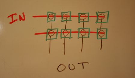
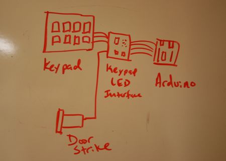
The keypad is actually built from two separate circuits that physically overlap. The input circuit is a simple keypad matrix. To read each button push, the Arduino brings one keypad input line high and checks the voltage of the four output lines in order. The diodes on the PC board prevent feedback across the rows and columns.
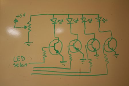
The RGB LEDs are lit via a completely separate set of circuits. Each row of like colored LEDs is brightness controlled by a digital potentiometer. The digital pot works just like a normal pot, but it’s digitally controlled by the Arduino. Meanwhile, each column of LEDs is activated by a separate transistor. By quickly changing the resistance and stepping through the columns, each LED will appear to be individually controlled.
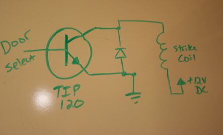
The door strike circuit is pretty simple. Since it contains a coil, we’ll treat it like the coil of a stepper motor and use a TIP120 transistor to supply the power. When power is removed from a coil, the collapsing magnetic field creates a current within the coil. To keep the TIP120 from burning out, we’ll add a diode to handle the surge created by the field breakdown.
update: [Triffid] pointed out that the diode is better placed in parallel with the coil to handle the transient surge. He’s correct, but the circuit here has operated perfectly for several months, so you’ll be fine either way.
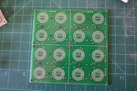
The traces for the buttons looked a bit challenging to etch at home, so we ordered this PC board that Sparkfun produces for their keypads. Sparkfun helpfully provides the layout for these keys in their eagle library, so you can make your own PCB if you prefer. For reliability, you’ll probably want to have it commercially produced. The board wasn’t really designed to break apart, but after a review of the traces and vias we decided that we could get away with trimming a couple of rows from the board.
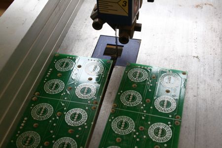
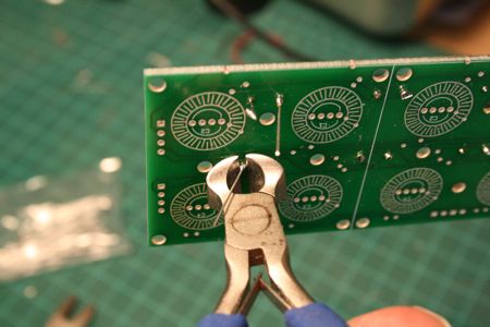
We carefully split the board down the middle with a band saw. If you look closely, you can see where some of the vias were actually cut in half. (A paper cutter might work in a pinch) Don’t forget to put on a mask to keep the dust out of your lungs.
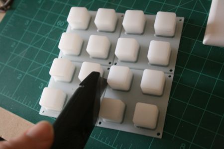
Cutting the button pad is much easier. The pads have pre-scored lines that just need a quick swipe of a sharp knife or scissors to separate them.
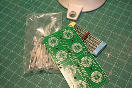
The new shorter PCB only needs a few parts: some 1N4148 diodes and the RGB LEDs. The silkscreen on the board indicates the direction and position of diodes and LEDs.
Once you solder on the 1n4148 diodes, cut them as close to the PC board as you can. Flat head cutters like these work extremely well. The keypad will sit on this side of the board and we want to make sure that it can sit as flat as possible.
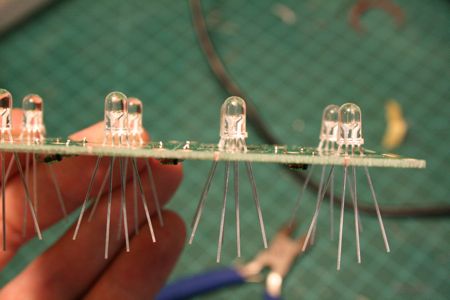
Install the LEDs in the orientation indicated by the silk screen. Carefully push them down into the board until they’re inserted just like this. If you let them stick up too high, they’ll interfere with the keypad buttons being pushed.
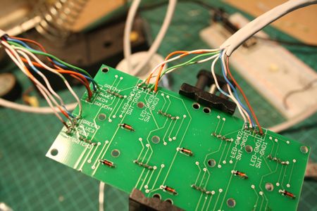
Once you’ve soldered all the LEDs in place, clip them flush as well. Then you’ll need to add some cable to jumper from the keypad to the interface board we’ll build. We used some old CAT-5 wiring. Since each axis of the board has eight pins, it’s perfect for the application.
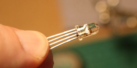
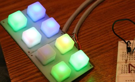
Each RGB LED has three LEDs inside the package. They share a common terminal and have a single separate lead coming out. Because they have different characteristics – that is brightness, current and voltage requirements, we spent some time testing out various combinations. We even murdered a couple of innocent $2 LEDs just for you. Hey, the other two colors are still usable…
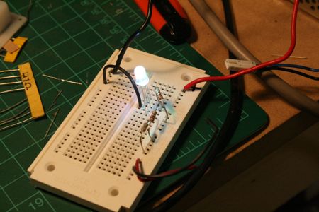
After some experimentation, we managed to find the right combination to create some fairly white light. The requirements will vary between manufacturers, but for the Sparkfun LEDs we found that a pair of 100 ohm resistors and a single 150 ohm resistor blended the red, green and blue fairly well.
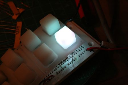
The color combination was hard on the eyes until we put the keypad over the LED to double check our findings. In real life, you can see some blending lines from the offset of each LED, but it still looks great.
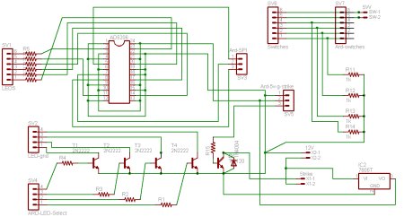
The circuit has plenty of components, but it’s pretty easy to build. We’ll break everything up by section to keep things easy. You can download the all of the schematics, Eagle project files, and code for the Arduino here.

The digital pot has six outputs. Each of these will power a row of red, green or blue LEDs, via a color matching resistor. The digital potentiometer wiring comes directly from this how-to. You can read it if you need more information, or use our quick version:
- Connect AD5206 pins 3, 6, 10, 13, 16, 21 and 24 to 5v.
- Connect pins 1, 4, 9, 12, 15, 18, 19, and 22 to ground.
- Connect pot pin 5 to Arduino pin 10
- Connect pot pin 7 to Arduino pin 11
- Connect pot pin 8 to Arduino pin 13
Grab four 100 ohm resistors and two 150 ohm resistors. Place them in the breadboard in a row with each end in a separate bus. (Across the center of the board is easiest) Connect the six LED leads from the keypad to one end of each resistor – reds get the 150’s and blue and green into the 100’s. Here’s the connection order we used.
- RED3 to a 150 ohm resistor to pot pin 14
- GREEN3 to a 100 ohm resistor to pot pin 11
- BLUE3 to a 100 ohm resistor to pot pin 2
- RED4 to a 150 ohm resistor to pot pin 23
- GREEN4 to a 100 ohm resistor to pot pin 20
- BLUE4 to a 100 ohm resistor to pot pin 17
![]()
To ground the LED busses, we’ll be using four 2N2222 transistors. The Arduino will trigger each transistor individually through a 1Kohm resistor. The collector of each transistor connects to a ground line from the keypad. The emitter of each transistor is connected to the ground. The four transistor select lines connect to Arduino pins 0, 1, 2, and 3. Yes, they’re marked Analog in, but it doesn’t matter.

The keypad switch matrix is connected in four columns and two rows. Each of the four columns gets a pull-down resistor. We used 1Kohm resistors for R11, R12, R13, and R14; one lead connects to the columns and the other is grounded.
Arduino pins 2 and 3 should connect to the two ungrounded lines, which are marked SWITCH3 and SWITCH4 on the PC board (5 and 6 on the schematic).
Arduino pins 6, 7, 8, and 9 should connect to the four output lines marked SWT-GND1, SWT-GND2, SWT-GND3, and SWT-GND4 (1-4 on the schematic).
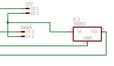
The final version of the board takes a 12VDC input to drive the door lock. We added a 7805 to drop the 12V down to 5V for the Arduino. You don’t need it for the prototype version unless you want to test the striker. The Arduino has an on-board regulator, but 7805’s are cheap and it helps reduce the load on the Arduino’s built in regulator. For code development, we just connected an LED with a resistor to the output line that will control the door lock.
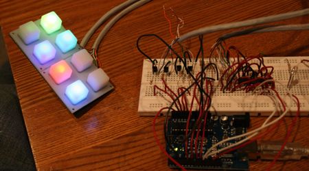
With everything wired in the prototyping board, it’s time to test things out. With any luck, you’ll soon be rewarded by the pulsing, glowing sight of several RGB LEDs under your tender digits.
Programming the Arduino is a snap. Just download the software for your OS here. Now follow the Getting Started guide to get the Arduino software talking to the Arduino board. Once you’ve enjoyed the blinking LED demo, come back here and get your keypad rolling.
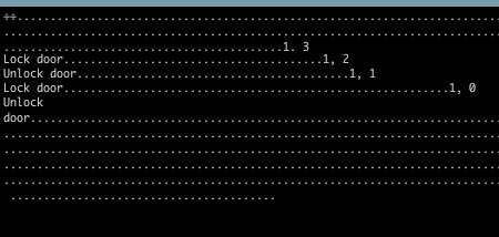
Once you’ve set up and tested your Arduino, it’s time to test out your prototype. Download the button_test code from here. Paste it into a new sketch and upload it to the Arduino. Click the serial console button and you should start seeing dots accumulating in the window. If you press a button on the pad, the Arduino should print a message to the console and toggle the lock output state.
Once your buttons are tested, you’ll probably want to try out your LEDs. Grab the RGB_light_fade routine from the same page and upload it to your Arduino. You should get treated to a nice little light show. This is our favorite demo because it really shows off the color mixing capabilities of the digital potentiometer.
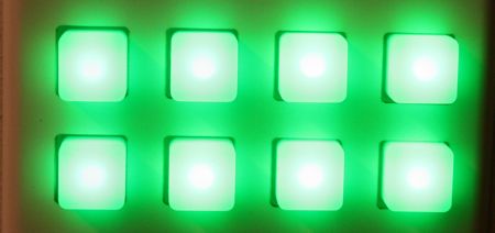
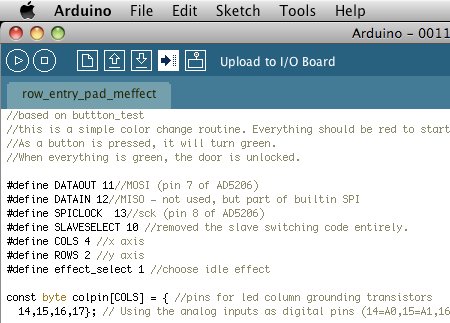
With your LEDs and buttons working, you can grab the row_entry_pad_meffect lock code from the same place and upload it. Now the keypad should start flashing blue buttons while it’s idle. On key presses, the keys will change colors. By entering the correct color code, the pad will flash green and unlock the door for 10 seconds. If you go over the limit counter, it will flash red for 30 seconds.
Next time we’ll show you how to make the permanent version of the keypad, walk through the code for the Arduino, make the PC board, cut a custom wall plate, and install the lock strike.


regarding the keypad, are the button colors randomized after each key press? How hard would that be to do? The code would be the same everytime, but the combination of buttons pressed would be different. Would help keep prying eyes from determining what the code was. Cool project. can’t wait for the next post.
The code should be easy enough to modify for that feature. I haven’t had time to mod it much beyond the basic function – it’s mostly to keep short people away from the tools rather than provide true security.
some of the blending lines (noted in the caption of the white mix test pic) and some uneven distrobution of light across the individual button can be taken care of by pre-diffusing the leds.
this can be done by sanding the led with fine sandpaper, or by simply cutting off or sanding down the tip of the lense with a rotary tool.
i had an incandescent lamp lit button i converted to LED. I chose a rotary tool cutting wheel to cut the tip off. The light is more even now. just don’t breathe that led dust either!
I’m only familiar with PICs, not the Arduino, but couldn’t the digital pot be eliminated by using PWM to drive the LEDs?
Very cool. not very familiar with the arduino but this looks very cool. As a low voltage installer this would be slick to integrate into a home security system.
@ edz
That should be the case, and would produce a much more simple circuit design. Wonder why it wasn’t used? To answer my own question, timers and such can be a real pain for beginners, could have been to simplify the code at the expense of the circuit…
Great project! Very high on the cool scale. (Yeah, I’m a nerd!)
Is that a standard switch plate, or did it come with the buttons and circuit board? (Just my luck, I would build the whole thing and end up with a duct tape wall plate. LOL!)
I would love to see the lights in a small programmable key chain, and an electric eye to receive the signal. Then it would work like a remote car lock. Who am I kidding, I would use it to replace the system in my wife’s car. She lost both key tags and the dealer wants a fortune to replace them. (To the dealer: Take blood instead of cash. It is easier for me to replace.)
Just like brad wrote in the first comment my first thought was that the key colors should either pulsate and change colors every 5 seconds(or less,,though one of each color must be present at any time), or change after each pressed button.
You could even make things harder and have them all randomly change colors, and then make key-presses valid ONLY when a key has a unique color.
The diode should go across the coil, not the transistor. In its current location, it will protect the transistor from reverse polarity, but not the overvoltage which the coil creates.
http://www.rentron.com/images/rely-drv.gif has the correct layout.
Almost correct, Provided there is a suitable large capacitor on the output line of the power supply and physically close to the switching transistor, that capacitor will act as a short for pulses (and AC). So, the diode is than (for the pulses the coil generates) effectively in parallel with the coil, protecting that switching transistor against over voltage. However, the capacitor may be stressed out over time (depending on the amount of energy released by the coil and the ratings of the capacitor) making the design “weak”. Also note that the polarity of the pulses from the coil hitting the capacitor will introduce spikes on the power line (they have unversed polarity)… As a result, it is common practice to have the diode connected in parallel with the coil.
Even when the TIP120 has an internal snubber diode, it is connected the same way as the external diode is in the picture, so it protects the transistor from negative voltage spikes only.
But the coil produces a positive voltage spike when the transistor is turned off. So if there is no diode over the coil, the voltage at the transistor can freely rise to whatever value it wishes. If it goes over what the transistor can handle (60V?), kaboom!
Depending on the coil inductance and DC resistance it has, different amount of energy is stored in the magnetic field and released differently when powered off. Some coils will work indefinitely and some will blow the transistor out the first time it is used. So add the freaking diode there, cheapskates :)
my first question. how difficult would it be to extend this to a 2 by 5 array, and have the 2 buttons in the added column be a clear and test button. ie, if you are entering the code, and you know you made a mistake, you can clear the code and try again. and rather than just testing the code in the programming code on each button press, just test it when the test button is pressed. this will clean up the usability a bit, and make it a bit harder to get into, as you cant just randomly jab at buttons untill it opens, you now need to know how long the combination is.
and my second question. how hard would it be to give some sort of audio feedback (ie. a beep) on keypress? (just a single beep, nothing that allows you to know the difference between each button like a phone).
this keyboard http://klawiatura.wordpress.com/ will be better ;) many keys many combinations
this is brilliant. I am going to built one immediately.
has anyone thought of doing something similar using the wiimote and projection?
An interesting modification to this design would be to add numbers to the buttons, and integrate numbers into the combinations. For example, one could use “blue-green-1-9-white-2” for a combination. If the colors were randomized every time, then an observer would be somewhat befuddled. This, of course, would not stand up to many repeated observations, since the numbers would be constant.
Very cool
very cool stuff.
am i missing something? i do not see the potentiometer in the parts list. am i just a complete electronics novice, or did it get left out? what is a good source to buy a potentiometer? (I searched sparkfun, and could not find any)
For the light switch cover, you can search google for blank lightswitch cover
This website has various sized blank covers
http://www.kyledesigns.com/category/.11_home_decor.1_switchplates.wall_panels_blanks/
Cool project! When is part 2 coming out?
Btw, if anyone is having trouble finding parts Digi-Key is always a good source: http://www.digikey.com/
Hmmm thoughts;
PWM requires fairly tight timing to get the colors to play nicely, which means your processor needs to spend it’s time playing timer on so many levels. (As infered by the article, the red LED requires a larger resistor, so you need to define different time values for the colors, and then adjust the other time slices as fractions of the base time…or, you could use a Serial Line Addressable Pot instead, set the value, and get back to change it when you can. ;-)
I like the idea of randomly changing the colors…if it’s not actively being used to unlock a door (or command some other system ;-), then I think it should be Blinky Light Art.
Pushing a color sequence, when the colors are ramdomly changing, would be tricky…but, freezing the color changing briefly, when there are buttons being pushed, would make it easier to push the rest of the sequence. But pushing the correct first color, might be tricky..so, maybe the first key is a ‘throw-away’ which locks the color change? Maybe it makes sure all colors are represented on the keys, in a random dispersal?
Clever hacks! I’d still add the blocking diode at the relay, since I’m Old School, and I used to play with bigger coils with lots of energy.
-Z-
what class would I take to learn how to use the schematics
electrical circuits and electronics
A great project! Just one or two things I’d like to ask. In the break up and description of the schematic, there are two parts that are never mentioned. One is where is ARD-5v-g-strike going and what is it? The other is, what is the value of R15? There are 14 resistors in the parts list, 15 in the schematic. Am I not reading something?
I would like to use the code for that randomizing light thing where the colors are the same but the buttons are different, if you develop it, would you please e-mail it to me @ support@insanelyrandom.info? Also I don’t know what tools you would use to make the switchplate besides the laser cutter, or a cnc machine(Both of which I don’t have).
Any Suggestions?
I realize I’m commenting on an old post — but PWM would be much easier. Forget the nonsense about playing with timers — most PICS / AVRs have hardware PWM peripherals that can be simply setup and then varied by writing to a single register. The change is immediate — certainly faster than writing to a digipot via SPI or I2C.
Hey i replicated it; and IT WORKS!!!!
http://sites.google.com/site/newinthepast/Home/rgb-combination-lock–boredom-over-christmas-break
hi..ermm this is absolutely cool..
i will try this project as my final year project at my colge..
so i hope u will help me a litte bit..hehhe
ermm i want 2 ask..
the arduino can be replace with the pic16F84A , can or not??
Is there a potentiometer in the parrts list, or is it in the arduino?
How much does one of those cost?
i just built one of these on my own. when i run the button test script it works, fine. when i run the script to test lighting effects it flashes one or two random patterns for a few seconds each, and then lights all of them to white. as in full 255 to each channel. is there anyone that could help me troubleshoot this?
Is there a way to clean the keypad? Ive had mine for a while (have not used it much), but the keys are becoming non responsive, and fidgety. Any suggestions? email me at: a a d e e 9 2 @ g m a i l . c o m
Completely new to Arduino here, but if someone would be kind enough to tell me if this application could possibly unlock a computer (really have no clue how Arduino interacts with computers) I’d be pretty appreciative.
Oh, and I’ll also be buying all the stuff necessary the next day. This. Looks. Awesome.
Thanks for sharing the information…
great Project
Hey is it possible if we can get the code onto a PLD(programmable logic device)? If so please contact me on how to!
Dear Author,
Had a few questions popping in my head..! Since Arduino is popular BECAUSE it’s an open-source platform, can we say the same about all the projects out here using the arduino board? Who owns the IP..the guys at run hackaday.com or the individual authors? What if I were to publish an article in a mag about this RGB Combination Door Lock..whose permission do I take..if at all I need one?
Thanks. Hope to hear from you soon!
I have almost no experience with electronics, but I’d love to work my way up to something like this. Can anyone recommend a website, book, or tutorial project that would make a good starting point for a novice?
You could start by getting an arduino and looking at the tutorials on the arduino or sparkfun websites. They are very informative about how t get started and have some basic projects that can help you get to the level to built this.
On another note, has anytime had the chance to try this project using only the analog outputs (PWM) of the arduino. I am wondering about the ability of the arduino/ATMega to precisely regulate PWM and perform the other functions at the same time. Using the dig pot definitely seems like an extra step, I just don’t know about internals of micro-controllers.
Nice write-up and it looks great. But I’m with Triffid and Jeppe. That diode you got on there now isn’t doing what you say it’s doing. It may work fine now, but (and really, I appreciate the fine work you put into this thing!) you shouldn’t tell others to set it up the same. Even if you’re still under spec of the TIP, that coil can/will act erratically when you cut the voltage to it. And though short, the forward voltage could be of magnitudes higher than what you put into it. That diode where it is now won’t do anything for you and it’d be a pain if you can’t open your door as a result of your transistor burning up.
But really, appreciate this cool project!
It is very nice.I like it.It is very usefull me for my job
MAN! very great project!! but i have the same Wolf’s doubts, i will copy his questions
” Just one or two things I’d like to ask. In the break up and description of the schematic, there are two parts that are never mentioned. One is where is ARD-5v-g-strike going and what is it? The other is, what is the value of R15? There are 14 resistors in the parts list, 15 in the schematic. Am I not reading something?”
Please, answer as soon as you can. thank you
i was wondering if anybody got back to you on your question about the RGB combination lock? i was wondering the same thing, thanks.
i like this method of doing . but i didnt understud that how the signal passes and etc
can you please post the complete list of materials in this project..? thank you.. I’ll be waiting for it ..
very nice
Your website is the reason I got into electronics and the Arduino.
Definitely going to make this.
Thanks
It is good for those who never went for there classes they can use it as their project
thanx and regards,
prabhakar
Do you have part two posted? do you have the link for it
Can I possibly add a bluetooth so that I Can possibly send the code lock wireless?
it is gud……
Hi, i can´t get working the 4 columms, only 3 columms at the same time…
Any ideas?
@luis are other things working imean lock/unlock have u used same circuit
where does strike is connected to arduino??