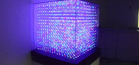
Adaptive Computing, a cloud management and high performance computing outfit in Utah, needed something really cool to bring to their trade shows. Something that makes order out of chaos, and demonstrates their attention to detail in the midst of miles of wiring. They decided building the largest non-commercial LED cube would be a good project, and thus the 16x16x16 All Spark Cube was born.
The All Spark Cube was constructed using 10 mm RGB LEDs wired together with three-foot lengths of 16 ga pre-tinned copper wire. In this video, [Kevin] shows off the process of constructing a single row; first the LEDs are placed in a jig, the leads are bent down, and a bus wire is soldered to 16 individual anodes per row.
The hardware for the build uses 16 Arduino Megas with a custom-made shield powering a 16×16 LED grid. The custom shields provide the 24V for the LEDs, 5V for the ‘duino, The Arduino boards communicate to each other through an RS485 connection, and the entire cube is connected to a computer through an RS232 serial connection.
The software is, admittedly, still a little janky. [Spencer] and [Thomas], the Adaptive Computing volunteers that are working on the control system, are still having a few problems getting logos and animations to display. They have managed to create a control app to draw individual pixels, as seen after the break.
Not bad for nearly a mile of wire and a summer’s worth of work, huh?
[youtube=http://www.youtube.com/watch?v=O-4EQPauUCI&w=470]


From a comment to another post: http://www.seekway.com.cn/e/3D/ledsys28.htm
You Know we actually bought a 16x16x16 from seekway initially. It was novel because it only had 1 wire running through it. We sent it back because it was less than impressive. 3mm leds, and the software was a joke.
My thoughts exactly. World’s largest? Do a little research before you try to make that claim.
That is amazing,but i cant stop thnking this would be aq very good use of an FPGA or CPLD.
I recon this 32x32x32 led cube is slightly bigger…
http://www.youtube.com/watch?v=f1YNyQqbiF0
oh, that’s better.
Let’s wait for the 256x256x256, it will be the start of a real new display technology.
What the world needs now is some machine to assemble all the leds, or some way to solder smt leds on a glass circuit board.
I am doing a RGB 16x16x16 led cube, but because of handwork there are some bendings as a deffect. the 256x256x256 cube will contain 16777216 leds. If there is no technology to help you, one live won’t be enough to do it :)
Transparent LED screens makes this tech redundant. Just layer them . Theres your technology. My higher resolution. Much “easier” assembly.
It would be a bitch to replace one burnt LED.
You know, we have had a couple burn out because we are running them slightly higher voltage then they are rated for. Since each panel is pulled out like a plate from a bee keeper’s beehive, it isn’t too bad to replace a led.
@spuder
That’s awesome. Way to think ahead.
They said “non-commercial”. Of course there are going to be bigger ones available commercially.
Replacing an LED on one of those chinese “cubes” looks fairly easy as they are not rigid cubes, but individual curtains that hang from the top, each just one layer thick and a couple LEDs wide.
25’000 Spheres, 12 LED each: 300’000 LED in total.
5 x 5 x 1m :)
http://www.youtube.com/watch?v=7toXDJZfxug&feature=related
Project Site:
http://www.nova.ethz.ch/
why so much Mega? :S
A teensy 3.0 should make it work fine ^^
All 4 of us that build this are hobbyists, and not electrical engineers, so we had to keep it simple. Arduino Megas were the only solution we could find with enough pwm ports, and that we could get up and running without an EE degree.
This. So. Much. THIS^
Awesome!
It’s really nice to see people with inspiration to do something just get out and do it, figuring out what they don’t know along the way. So many people think things are lock away behind technology that they’ll never be able to figure out.
Great build!
I totally disagree with your EE sentiments, thinking for yourself is not exclusive to EE’s: http://lmgtfy.com/?q=pwm+led+driver
SIIICK build! Let’s hope they find a way to get some more attractive animations in there! The 32x32x32 above is epic tho… China…
The problem I see with all these cubes is they use DC so have massive power rails. They could probably get away with much thinner wire if they would use ac, add in some “troll physics” and you get a strand of leds with two wires, and ability to address them by frequency.
Thats a good idea. We experimented will several gauges. Starting at 22 ga down to 14 ga. We found anything thinner then 16 was too flimsy. The panels are suspended like an inverted honeycomb, with no structural support between them.
Actually, this cube only draws about 90 watts at 24 volts and that’s only when all LEDs are on full white. It mostly runs well under 30 watts. The wire gauge is for physical support mostly. Use of AC power wouldn’t reduce the need for larger wire for other reasons.
16 Megas? Wtf? Totally unnecessary.
I agree. Some programmable logic would have been a better choice and no communication between the MCUs needed. That said, i don’t know how to program FPGAs and CLPDs so i personally wouldn’t be able to do that by myself.
Now make it bigger and run some sort of Conway’s Game of Life 3D on it!
3d snake and 3d tetris are in the works. We also have plans to incorporate a kinect into it.
Second request for Conway’s Game of Life. I promise, you won’t regret doing it :-)
FWIW, the claim is that it is supposed to be the largest non-commercial LED cube..
..made by a COMPANY in Utah.
I prefer my noncommercial to be done/doable by an individual not and not to drive sales even if indirectly, but that is just me.
Actually, it was COMMISSIONED and SPONSORED by a company in Utah called Adaptive Computing who builds software, not LED cubes.
I was badly distracted by the dude’s fingernails.
Sorry, I didn’t mean to report the top comment. I was on my phone and tapped it by accident. There’s no undo function?
Those custom shields look way over engineered.
Why not replace each Mega with two Max6954 or Max6955 chips? Each chip can drive 128 LEDs, and they can be daisy chained.
Simpler, cheaper, all driven from a single controller (eg rPi) and avoids the messy communications between the Meggas.
You are quite correct, although not about the over-engineering. The engineering is really quite simple. The problem comes with the size of the matrix. I originally attempted to use TI5940’s as low side drivers. Lot’s of advantages there. But the time it takes to serially transmit 192 bits per color per row, 256 rows per frame, at 60+ frames per second made that impossible. Assuming I could have gotten the serial bit rate required (which I couldn’t with the Arduino) the LEDs would have been on for such a short duty cycle that they wouldn’t be very bright (or would flicker badly). So I modified the design so each controller only needs to manage one panel (256 LEDs) and created a communications requirement between the panels. Trust me, I would have preferred to use a single board design but ran out of time. I built this entire unit in 55 days!
H\\When will someone make a LED cube that can be interfaced with a PC video card? I imagine making more complex animations at higher refresh rates will be possible and easier. The image quality will be better because you can have finer control over color, higher refresh rate as well the option for effects like AA. Finally you would be able to have interactive and dynamic displays.
I imagine the programming on the computer end would be pretty straight forward (I am not saying it would be easy, just that the method for generating and outputting this information over a video card seems obvious (the programming to get there might not be so easy). As for the electronics side I have no idea and am curious about what others think.
A 64^3 cube is close in number of RGB points to a VGA size display 128^3 is close to 1080P. If you wanted to drive a 256^3 display you will probably need to use more than one video card output (AIUI DVI supports a maximum of 1920*1080*3 at 50Hz That gets you about 37% of the way there.
Subscribing to updates, theres gotta be an easier way.
How much time and money would this take to build?
We just added a wordpress plugin to make subscribing easier.
As for the cost, we haven’t shared the bill of materials, but I can tell you it was $800 for the LEDs alone! Total time was 7 weeks. By far the hardest part was soldering. Each panel took two people 6 to 8 hours to solder, not including trimming LED legs, wiring the ribbon cable and troubleshooting bad LEDs.
Kevin, The head engineer commented on the cost on the AllSparkCube.com forums. If you’re still interested you can read his response there.
FYI my video card states that it supports a maximum of 16384×16384 via its framebuffer. This is a mid-level card.
Because of that, I think it shouldn’t be too hard on the video card to run two DVI (or 3 in the case of ATI cards) to get more of the pixels out.
I wonder if anyone has ever tried stacking OLED displays to make a high resolution LED cube.
oled displays are not transparent like lcd
You just sparked a thought about stacking up a series of POV displays to get a 3D like effect in a cylinder. Might even be brighter and clearer than these LED cubes. Would probably be easier to wire up and drive than these giant cubes.
nice. I have a 3d point manipulation library if your interested, Love to see some 3d/2d shapes bouncing around int here.
Excellent, please feel free to contact us on Github or via email so we can take a look at your code and see how it would fit in our programs.
@ Spuder – When I look at that cube I just have to think to myself, “Giant Rubik’s Cube Game”. Just saying.
Brilliant, that is going on the future revision list. Someone else mentioned lunar lander as a possible game.
How about a 3d image of a face or a dancing baby or woman.
where can i buy one
This is really a cool
Kudos on all the work that brought this to life, but the control system needs an overhaul. If I went to a booth called “Adaptive Computing” and saw this I’d very much want to see their ‘solution’ that drives it. 16 Arduinos.. is kinda silly/expensive/inefficient.
16 x ~$60 = $960 in arduinos alone.
A uC -> FPGA -> common anode driver IC, makes way more sense.. even a single uC to a giant array of shift registers seems more robust and would likely have less ‘problems’
There are plenty of problems with making volumetric displays from discrete LEDs.
First is as size goes up the LEDs deep in the display become increasingly obscured by the LEDs and wiring towards the exterior.
Second is density. The display cannot have the LEDs too close together without obscuring deeper ones.
Third is cost, both in materials and labor/time to put it together.
Until someone comes up with technology to make LED flat panels that are completely transparent, super thin and can be stacked directly together, these light cubes will remain a low-resolution curiosity of little practical use.
Another way to make a truly useful volumetric display would be to “grow” it as a solid. High resolution 3D printing might accomplish that, but it’d take a large speed increase along with using a large number of production machines to make it economically feasible.
We’re still a long way from the 3D ‘tanks’ of the SciFi novels of the 1970’s.
Please report to charm school for basic remedial social interaction skills.
Come on. Even if you weren’t completely impressed by this like I was you could at least acknowledge the amount of effort and drive it took by simply not posting anything.
bravo … seconded
The hardware looks nice, but the software really lets it down. Apart from expanding squares, the demo video had pretty much all of the LEDs on so what we saw was a cloud of light. It’s not always a case of ‘more is better’ with the display. Any chance of seeing some 3D objects on (in) it? Even a rotating wireframe cube would be good.
I couldn’t agree more, Spencer and I are working really hard on the software. The problem being that neither him nor I are very good programmers. If you have any expertise in the software department we would love to get some tips. Nonetheless, in time we will definitely have some more interesting animations and uses.
8-bit games I’d like to see on this:
3d Space invaders
3d Pong!!
3d Breakout
3d Pacman
3d Donkey Kong
3d Galaga
…
I was at vmworld in SFO this year, can’t say that the cube was doing anything. it was on but not cycling or displaying much. It was a static cube of random color. I wondered WTF it was other then eye candy. Had it been doing anything the video was showing I don’t think the crowd of geeks would have left it (moths to a flame), as it was it was a passing curiosity I snapped a few pics with the cell phone and moved on knowing someone got carpel from the solder job.
Contrast that to the convention centers display in the “hang” space that was tied to the vmworld twitter feed. It was a cylindrical display in the center of the room made up of around 200+ or so led panels(not tv’s but LEDs as each pixel) all facing outwards hung from the ceiling displaying the real time feed. I saw more people stopping and taking pictures of the back side of that display after they looked up under it to see how crazy it was. each row of displays some 8-10 deep or so and about 30 around. You could see they were on some sort of bus/matrix feed as each display unit had its own three digit number. Not sure what fed the beast but it was neat in its own way.
From the video and the subsequent comment videos – It appears to be:”Not about the size of your display, but how you use it.” ;) I think if you ran the 32(3) demo on an 16(3) it would really step up the show.
From now on – all LED cubes will be judged by how they display the attack on the deathstar. :p Oh – I guess that’s just for spinning displays…
– Kris
Oddly enough the small ones had a way bigger wow factor effect on me.
Same effect as how a 2D displays made from for instance 80 LED has a different impact than the OLED display on a phone even though those are LED and many many more of them.
Why are people not using these to display the Death Star plans?? I’m so disappointed!